Solving 4 Critical Valve Body Failures: Advanced CNC Milling for Smoother Shifts & 60% Less Leakage
Introduction
The relentless drive for smoothness, responsiveness, and efficiency in modern day automatic transmissions depends on the accuracy of the hydraulic control unit, commonly known as the valve body. This “brain” of the transmission controls the flow of fluid to operate the gears. The problem with the accuracy of the valve body is the “silent failure,” whereby a component of the valve body will pass all the static tests but will still cause harsh shifts, pressure fluctuations, and leakage during the bench and vehicle tests.
The cause of the problem with the accuracy of the valve body is the outdate “discrete hole machining philosophy,” whereby the feature tolerances of the valves are consider, while the function of the valves as a complete hydraulic system is ignor. The micro-burs, thermal distortion, and flow path surface finishes all affect the precise logic of the hydraulic control. This article will discuss a paradigm shift from “feature manufacturing” to “hydraulic performance injection” by the use of advanced CNC milling techniques to inject a dramatic reduction in leakage.
What Are the Root Manufacturing Causes of Internal Leakage and Flow Inaccuracy?
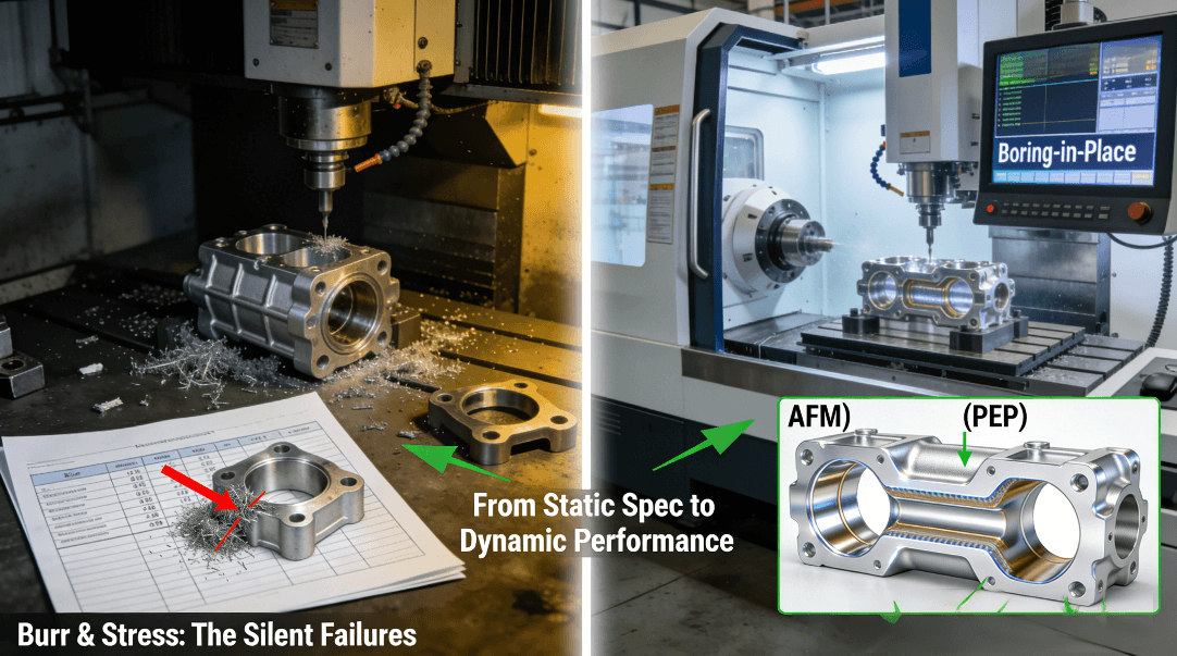
The root manufacturing defects that lead to internal leakage and flow inaccuracy are threefold, all of which are not detectable by static inspection methods. Firstly, loose burrs in the cross-holes can become loose, acting as an abrasive that can score precision spools or change the flow area. Secondly, stress in castings or machining, which does not go away in heat treatment or in the rise in temperature, can lead to “bore walk” or excessive spool position variation of greater than 5µm, thus rendering the seal useless. Finally, surface texture, which is not related to a single value of Ra, can result in increased “breakaway friction” in the spool, thus leading to lag in response.
- The Insidious Threat of Burrs and Contamination: Burr contamination is not just a cosmetic problem but rather a systemic one. The high-pressure, recirculating fluid in a transmission is not a place where a loose aluminum burr has any business being, as it functions as a form of lapping compound on already-hardened steel. The emphasis that the industry places on fluid cleanliness, as described in SAE International, serves to highlight that burr control is not a choice but rather a necessity in achieving hydraulic control precision.
- The Unseen Warping from Stress: A dimensionally perfect part, even at 20°C, may be catastrophically out of spec when in the operating environment. Material removal, particularly in machining, puts in stresses that, if not carefully controlled through strategic machining, will relieve stresses over time or with temperature, causing the bores to warp. This warping, though not detectable by the CMM at room temperature, directly relates to the problem of leakage paths and binding in the field.
- Surface Finish: Beyond the Ra Number: A “smooth” surface may not be functionally adequate. A honed surface may have an acceptable Ra, but if the cross-hatch pattern is not correctly align, it may hinder fluid flow or create unwanted friction. The objective, of course, is to create a surface that allows for the most efficient laminar flow, allowing the spool to rotate with the least amount of stiction. This, again, involves moving beyond basic milling techniques, as in the construction of the modern hydraulic valve body.
How to Ensure Valve Bore Position and Cylindricity Through Multi-Axis Simultaneous Machining?
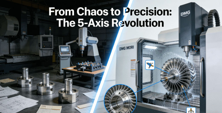
The first solution to the problem of geometric drift is the removal of setup changes. This is achieve by the simultaneous machining of the entire valve body. A complex six-side component, by 5-axis simultaneous CNC machining. This eradicates the cumulative effect of re-fixturing and provides one single datum for all important features, from mounting holes to the most precise spool bores. The approach changes from “milling many holes” to “machining a complete hydraulic manifold” in one single operation.
1. The “Boring-in-Place” Strategy for Critical Features
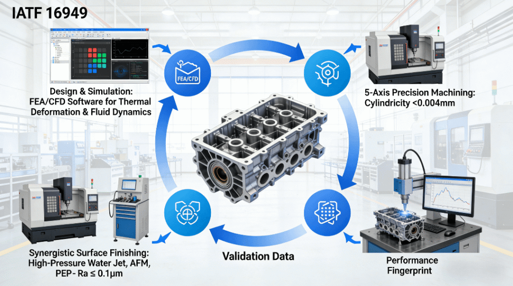
In the case of IT6-grade spool bores, precise boring operations are use to machine the bores directly on the machining center. A closed-loop process is achieve by micro-adjustable boring tools and on-machine probing. Where the bore is machine, measure, the offset automatically compensated, and a finishing pass made. This process maintains cylindricity and straightness to less than 0.004mm, a tolerance impossible to achieve with setup changes.
2. Proactive Thermal Compensation for Real-World Stability
Intelligent machining techniques also account for the thermal instability that occurs during the machining process. By using Finite Element Analysis (FEA) models, the predictable instability that occurs during the machining process is simulate. And the tool path is automatically adjuste for these changes during the finishing process. The part, in essence, is machine to the wrong shape at room temperature. But it springs into the perfect shape at the proper temperature, ensuring performance. This approach to ensuring the perfect geometry in the finished part represents the heart of the new automotive transmission valve body CNC milling.
3. Unifying Design Intent and Manufacturing Execution
This capability represents the ultimate alignment of the digital model with the physical part. As the intricate relationships that exist in the computer model, including bore locations, sealing surfaces, and mounting surfaces, are preserved in the finished part. The finished part represents a true leap in Precision Manufacturing Technology, as the hydraulic geometry of the finished part is not only accurate but also stable. Providing the ultimate platform for the fluid dynamics that control gear shifts.
What is the Definitive Process for Cross-Hole Deburring and Flow Channel Surface Finishing?
Hydraulic purity can only be achieve by conducting a multi-process assault on surface defects. The best practice finishing sequence follows a four-level hierarchy. First, CAM-level prevention optimizes tool exit path geometry to reduce the incidence of burrs at the outset. Second, high-pressure water jetting (in excess of 1000 bar) forcefully clears the majority of the loose debris and incipient burrs. Third, Abrasive Flow Machining imparts a uniform abrasive action throughout the internal geometry, radiusing edges and micro-polishing the surface to eliminate the turbulence which can impede fluid flow.
1. The Transformative Role of Abrasive Flow Machining
AFM is the key to the successful execution of surface finishing operations. AFM can access areas which are otherwise inaccessible to tools, which can then be use to smooth out transitions and remove the recast surface which was create by the machining operation itself. This operation not only deburrs the surface but also imparts beneficial compressive residual stresses onto the surface, which can extend the fatigue life of the component. It can also transform the internal flow channel from a rough machined path to a hydraulically efficient channel.
2. Achieving a Metallic “Mirror” Finish
The final step to achieve the best performance is often Plasma Electrolytic Polishing. When dealing with stainless steel or aluminum parts, this process can eliminate microscopic peaks on the surface, achieving Ra values of 0.1µm or less, and at the same time creating a passive oxide layer to enhance the parts’ resistance to corrosive environments. This extremely smooth surface finish reduces the points of adhesion of impurities and further reduces fluid friction, which is essential for the sensitive valves use in high-precision hydraulic control machining.
3. A Scientifically Validated Process Chain
It is essential to consider the relationship between the choice of the materials and the processes used to finish them. Sources such as the MMPDS Handbook provide essential information regarding the response of materials like aluminum alloys to machining operations and the processes applied afterward. By taking a scientific approach to the choice of the finishing chain of processes, the final choice of materials for the CNC machined parts of the hydraulic valve bodies can be such that they are not only clean but also metallurgically optimized for the task at hand.
How to Achieve Dimensional Stability and Cleanliness Control in Mass Production?
A transition from the perfect prototype to the reality of mass production requires a controlled environment. This is achieve by developing a system with three pillars. First, statistical process control is employe to monitor the processes at 100% for critical features to maintain the Process Capability Index ≥ 1.67. Second, the clean room assembly protocol is strictly adher to by performing multi-stage ultrasonic cleaning and drying of the parts before assembly in a clean environment to achieve particulate levels as defined by ISO 4406.
1. The Framework of Quality Management Systems
Consistency in mass production is achieved by system and not by individuals’ skill level. Adherence to international standards such as ISO 9001, IATF 16949, and AS9100D defines the framework. These management systems require documentation of procedures from incoming material inspection to preventive machine maintenance, with full traceability. This transforms the artisanal skill level to industrialized consistency, which is the benchmark required by the Automotive Component Manufacturing sector.
2. Data-Driven Traceability and Tool Management
Each component comes with a digital “birth certificate.” A manufacturing execution system connects each machining process to every tool used and every result achieved. This approach, combined with smart tool life management — replacing tools based on actual wear, not clock time — prevents problems before non-conformance occurs. This level of control and precision is what makes a true partner in the business of precision automotive CNC milling.
3. Sustainable and Responsible Manufacturing
True excellence in modern manufacturing involves environmental responsibility. Adherence to standards such as ISO 14001 ensures responsible chemical, coolant, and waste handling in processes such as cleaning and finishing. This level of commitment to sustainable practices not only helps our supply chain partners stay ahead of regulatory pressures but future-proofs our supply chain as a whole, aligning with the values of leading OEMs seeking a custom valve body manufacturing partner.
How Do You Validate the Dynamic Hydraulic Performance, Not Just Static Dimensions?
The static dimension approval is just part of the ticket price, but the dynamic hydraulic performance validation is the ticket to get into the show. A validation pyramid has three tiers. 1: 100% functional testing on all valve bodies, looking for any defects. 2: Dynamic bench testing on a hydraulic test bench with live spools and solenoids. 3: Authority certification, with periodic samples being sent out to a certified authority to obtain cleanliness certification (ISO 4406), as well as material analysis.
- From Leak Test to Performance Fingerprint: The leak test is not sufficient on its own. The advanced test equipment mimics actual operating conditions, varying pressure and temperature to monitor the valve body’s reaction. The end result is a fingerprint of the valve’s performance, demonstrating that it will operate as required within the transmission.
- Closing the Loop with Simulation: The validation data is fed back into the digital twin. The results of the physical tests are compared with the original CFD and FEA simulations that were run before the design was created. The differences are analyzed, and the simulation is made even better. This closed-loop approach between simulation and reality constantly improves the accuracy of the “performance injection” process, saving time and reducing risk in future designs.
- The Business Case for Rigorous Validation: This level of testing is an investment in brand protection. It virtually eliminates the risk of field failures, recall expenses, and the damage to reputation that comes with them. Especially when it comes to the hydraulic control unit. By giving the OEM a complete performance picture, the company is not just a supplier of parts; it is a trusted partner in the entire Automotive Hydraulic System.
Conclusion
The process of manufacturing exceptional hydraulic valve bodies has evolved from a precise art of hole-making into an engineering science encompassing fluid dynamics, materials science, thermal management, and — above all — exacting process control. Instead of simply striving to satisfy a print, we are now striving to deterministically “inject” definitive hydraulic performance characteristics such as smooth shifting, instantaneous response, and lifetime sealing into the finished part. This requires a manufacturing partner that possesses a deep and vertical understanding of simulation, multi-axis machining, synergistic finishing, and validation.
FAQs
What is the typical lead time for machining a prototype transmission valve body?Normally, the usual lead time for machining a prototype valve body is 5-7 working days. This timeline covers the processes of machining deburring cleaning, and inspection. However, under certain circumstances, it might extend up to 10-12 working days due to the complexity of the part or requirements for special materials/coatings.
What is the precision achievable on bores in terms of tolerance and surface finish on high-performance aluminum valve bodies?
Here’s what precision levels can be reached: Top OEMs can produce parts within the IT6/IT7 tolerance ranges, which correspond to 0.008mm to 0.015mm. Cylindricity can be controlled to about 0.005mm, while positional accuracy can be maintained within 0.01mm. Surface finish can be as fine as 0.2m to 0.4m Ra by using honing and superfinishing methods. For extremely critical situations that demand minimal leakage and friction, surface finish can be further improved down to 0.1m Ra.
How is internal cleanliness verified, and what standards are followed?
The internal cleanliness of the system can be verified by particle counting with a flush solvent. The cleanliness level can then be reported to a specified standard such as ISO 4406, 16/14/11, or NAS 1638. This should be achievable by the manufacturer with the help of a reliable third-party testing organization to carry out the test.
Can the manufacturer give feedback on my valve body design to ensure manufacturability and performance improvements?
Yes, an effective partner should be able to provide a Design for Manufacturability analysis, which would include the detection of burr risk, the determination of datum strategy, optimization of the sealing groove, and the implementation of changes that would be beneficial in terms of reliability and cost, without compromising the hydraulic performance that was originally intended.
Do you provide tested sub-assemblies, or just the machined valve body?
Capabilities vary, ranging from precision machining of the valve body, with some organizations offering plug-and-play assembly of the entire module, including the spools, solenoids, and seals, followed by comprehensive testing of the assembly.
Author Bio
The information presented in this article is the result of extensive, hands-on experience in precision manufacturing, specifically with regard to solving difficult hydraulic component-related challenges. The information presented is the culmination of taking theoretical performance targets and applying them as manufacturable, reliable solutions in the field of engineering, as LS Manufacturing is a precision manufacturing partner that is dedicated to working with engineers to take difficult hydraulic designs and make them a reality as high-performance, validated solutions.